Rochester Fuel Gauge Sender -NOT SUITABLE ! corrected again

blimpy

New member
NOTE WELL..... THE ROCHESTER SENDER DOES NOT FIT MECHANICALLY AND THE RESITANCE IS BACKWARDS..
O = empty RATHER THAN 0=full

----Thanks to RonM for pointing out that I had that posted wrong for a week or two... ron I was looking at the wrong post!---

SO THE COMMENTS PREVIOUSLY POSTED WERE WRONG WRONG WRONG....

TO MAKE IT FIT.. YOU HAVE TO GRIND 1/8 INCH AROUND THE ENTIRE CIRCUMFERENCE
AND YOU WOULD HAVE TO USE THE ROCHESTERS IN PAIRS, and have Backwards Reading Guages !!

FAR BETTER TO REPAIR YOUR STEWART WARNER SENDERS.. OR CHANGE OUT THE WHOLE SHOOTING MATCH
SENDERS AND GUAGE ALL AT ONCE.

INCORRECT COMMENTS HAVE BEEN DELETED BY THIER AUTHOR in the interest of safety and common sense!
------------
My desire is to " stay original" which luckily for me is also the cheapest way to go.

No doubt the capacitive tube type system is the most accurate, with all manner of warning light
options, AND BETTER ACCURACY.
 
The following is an excerpt from the extensive Bellanca Cruisair Maintenance and Service Manual, 6th ed.:

TM-5-4210-230-14P-1_922_2.jpg

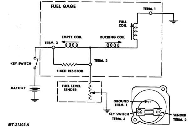
The electric fuel gauge system consists of two basic components--the instrument cluster mounted gauge and the fuel tank sending unit. The tank unit controls the gauge and the gauge registers the quantity of fuel in the tank. The two units are connected electrically as shown in Fig. 17. This air core type fuel gauge consists of three (3) copper wire coils wound around a plastic bobbin containing a magnet and spindle assembly. Attached to the magnet and spindle assembly is a pointer which indicates fuel level. The fuel gauge requires a 0 to 90 ohm resistance sender to operate. The sender is the tank unit and consists of a float and arm assembly and a variable resistor. The sender's resistance is controlled by the position of float and arm assembly. A full fuel tank raises float to its highest position. At this position the variable resistor has a resistance of 88 ohms. With an empty fuel tank the float assumes its lowest position, creating a sender resistance of less than 1 ohm.
 
OK, the above is NOT from the extensive Bellanca Cruisair Maintenance and Service Manual, 6th ed.
I got it off the web - International Harvester fire truck manual - I think. But the circuit is the same as the Cruisair except the Cruisair has battery voltage supplied through a resistor to reduce the voltage for the 6 volt gauge. Voltage supplied will not change the reading much. The reduced voltage is to avoid overheating the gauge's 6 volt coils.

With the schematic in front of me, it is easy to see that a gauge of this type could be tweaked up scale by adding a resistor across terminals 2 and 3 in the drawing if needed.

ron
 
FYI Air-Parts of Lock Haven repairs all this stuff. 570-748-0823. I had them do the fuel gauges and senders from a C-195. Excellent job and they worked like new. I just had them do 1966 Cherokee old style gauges and again beautiful job.They are not super on the turn time but well worth the wait. No need to reinvent the wheel just repair it. Lynn the crate 8)
 
Gee guys, I'm an electronics/ radio tech ( avionics, broadcast, marine com/nav) and an IBEW electrician.

so I sure as shooten know how the thing works !

But thanks the diagram will be useful to others reading the archive.

I guess I could send out my old worn out stewart warner sender to have a new resistor installed..at great expense...
but when I can buy the mechanical and electrical equivalent off the shelf brand new for $ 20 bucks... why bother ?

Yup... I can tweek the value of the dropping resistor to get a full scale reading.. since my resistor has aged,
and the wiring tests fine... or I can replace with a brand new 12v guage . I will see what I can do...but safety wise
and probably legally... the new guage is probably the only "good" option.
 
Well, I'm crushed. Nobody liked my reference to the: "extensive Bellanca Cruisair Maintenance and Service Manual, 6th ed.:" ( my version of droll humor) :)
The point is that the only approved maintenance data specifically for a Cruisair is a few ancient sheets with cryptic references to things like Univis #5 or whatever, that no one has ever heard of, and certainly no useful explanation of the fuel gauge .
Thus the gauge schematic. The fuel gauge circuit is simple but tricky. It works from the BALANCE of 2 currents. It's clear that if a a feed resistor were used, its changing value will have little effect on the position of the fuel indicator reading. In the case of the Cruisair, a feed resistor IS there to keep from smoking the 6 volt meter with 12 volts. Also, the resistor on the back of the meter is NOT the voltage reducing resistor. It's the empty coil shunt resistor - at least on my a/c. If you have 12 v or so on any gauge term, it is being fed direct and your gauge may have already gone away.

BTW, Larry, I assumed that you were OK with juice from your prev posts. However, I am crippled by Thevinen's theorem and and a design background and need schematics to think. And, as I said, the fuel gauge circuit is a little tricky.
But maybe, for those without the background for this kind of stuff, just do as Lwford suggests and call someone up and have them fix it. Do that regularly, of course, and you could soon have a $200,000 Cruisair. :shock:

As far as the tormenting legalities of replacing the original cheap automotive part with another brand functionally identical cheap automotive part, a logbook entry should work (minor alteration), but some might say a 337 is needed, particularly if the circuit is changed with 12 volt meter eliminating the feed resistor.
 
RON!

Thanks for the internal schematic of the guage.

Yup it is an interesting circuit/mechanism... embracing some of the elements of
a bridge or T pad.. and also an electro-mechanical ( or inductive) balancing act.

In the end I took apart my SW sender.. and found I had 3 separate "failure modes"
but none of them were an open or mechanically "wrecked" resistor.. so I was lucky and it was
easy to fix.

I will post repair/service instruction separately.. so they can be found easily in the archives.
 
OK.
I found that the fuel gauge reference for both Stewart-Warner sender ( get'em at summitracing.com) and Rochester sender (Spruce) are 0 ohm empty/ 90 ohm full.

There is another Rochester standard that is mostly a marine application. That sender is 240 ohm empty/ ~33 ohms full. That one won't work. It is backwards and the wrong resistance.

The screw patterns are SAE standard, so all will bolt up, but float arm directions can vary depending on the part number. Note: Larry(OP) says the Rochester flange dia. is a bit too big, so, at this point, I would just get the SW unit at Summit Racing if replacement is necessary.
Anyway, I will verify all of this at the hanger tomorrow.
 
Despite all my posts regarding the SW sender, I am with Larry Lowenkron.

I use my timer and my calibrated dipstick as my primary fuel management tool. But, the fuel gauge is required.. and if something goes awry in the fuel consumption department ( say a leak) the gauge is about the only way to know - except the glider like quiet just before the end of the rainbow, and the beginning of the long walk back.

Summit Be Damned. If you want to be a fruit salad, mix apples and oranges.

Ignore alien orders !

In the 1947 14-13-2 I fly... 90 ohms = Empty, and approx 0 ohms = Full

This is an absolute FACT !

Don't believe me ?
>>>>short across your sender with a clip lead and read your gauge.. then get back to me<<< !!!!

Yes!
There are Other Systems that work in the opposite sense.. but not the original Cruisaire equipment.
That was my whole point about the "substitute" I erroneously suggested. It's Bass-Ackwards Reading !!!


I dunno (anymore) about the modern SW.. they make several.. recheck the catalog - but assume nothing,
just because it's 90 ohms. :idea: :roll:
 
Vacuous comments aside :) , I discovered that the fuel gauge in my own plane had been replaced era 1960 with an after-market SW fuel gauge, likely when the panel was upgraded from original.
A friend at the airport happens to be a former Cruisair owner. So, when I mentioned the fuel gauge discussion, he gave me an original spare gauge which I compared with mine and it was obviously different.
View attachment 1
The pic is of an old original Cruisair gauge (I think)
Larry, does this look like one of your gauges?
I did some testing of that unit, and it is definitely NOT a 90 ohm gauge. It is more like a 0 to 40 ohm. However, it is not backward reading from the common aftermarket 0 to 90 system.
The readings were:
Code:
ohms    reading
0        empty (faint red line)
10       1/4
15       3/8
30       3/4
Finding a sender for this unit would be somewhere between difficult and impossible now, I think. Further, the scale is not so hot compared to my Stewart Warner replacement unit.

My own fuel gauge setup has always worked very well. I am happy to know someone in the past upgraded my system. With the replacement unit, the fuel quantity reading in the 3 tanks was always accurate and dependable. I like that. Since big iron guys go to great lengths to have accurate and reliable fuel quantity systems, they think it is important for safety and confidence. Me too.

Addl note:
There seems to be 2 popular aftermarket standards made by most aftermarket manufacturers. They are:
0 - 90 ohm and 240 - 33 ohm. Notice the reverse ohmage of the two. Either would work as long as the sender and gauge are the same range.

And thanks Larry for the email and expounding on the subject. We need a Wiki to put details like this in.
r
 
OK. I tested the 3 sender resistances with all tanks empty.
They are more like Larry's setup, in this case, between 120 and 150 ohm empty and, I am sure, near 0 ohms full.
Since, as in Larry's case, I don't see much out there with that range, I would have to anticipate replacing both indicator and all senders if there is a problem since none of the common stuff now-a-day is compatible.. or closely follow Larry's how to fix'm post on the subject of servicing the senders. I'll just hope it all works at this point.

So, there you have it, at least 4 or 5 "standards" for Cruisair fuel gauges.

Extracted from the web:
Which Fuel Tank Sender Do You Really Have?
0-30 Ohms (GM Type '64 and earlier)
0-90 Ohms (GM Type '66 'til '97 ) (Standard Aftermarket )
75-10 Ohms (Ford Type '86 and earlier)
16-158 Ohms (Ford Type '87 and later)
90-0 Ohms (Toyota and Nissan '85 and later)
240-33 Ohms (Standard Aftermarket)
 
excellent... ron.

No wonder we are all confused ! There are so darn many systems out there.
And, if they malfunction, it makes it even harder to figure out what you've got.

Which brings me back to the very first thing I did to dope out my system... I used a resistance substitution box
in place of the sender... to find out what range of resistance made my gauge "tick"
Remember I discovered that nothing would make it read higher than 3/4 !

I don't know how to post pics here.. but I will email ron a picture of the back of my SW guage.
and a picture of the top - the part you see if you remove the inspection plate on the top of the wing.

somewhere in my early "researches" I also saw a 0-140 ohm sender.

As I noted, IF you have the SW sender I have - and IF the wire stop is not adjusted to prevent it, then the
wiper inside the sender will travel to the bitter end of the wire wound resistor and onto the brass crimp
plate that secures the resistance wire to the screw terminal. When that happens ( wiper off the windings)
then you read the entire resistance.. which happens to be 140 ohms.

That could lead you to believe you have a 0-140 ohm system.. but probably not.

I think those bloody external resistors are at the heart of my calibration wierdness.. and perhaps ron's
but only empiracal testing will tell. Maybe the gauges just belong in the trash !
 
View attachment 1Ron... have you got a geiger counter ?

Your the hands on your gauge look suspiciously like the ones on my CHT... which has a radium dial
and I am sure was sourced ( by bellanca ?) from mil surplus.

So Maybe you DO have an original guage and mine is a replacement...?? hmmm

Somehow I came to understand that the originals were designed for 6v system, and had dropping resisitor
to function in our 14v systems. But that might be incorrect.

Like Mark Twain said of Americans ( more or less)

" I never met a people who knew so much, about so many things. I't a pity so much of it is wrong"
 
For what it's worth, Aircraft Spruce sells
10-02719 Mitchell Fuel Gauge $53.50
10-02172 Mitchell Fuel Level Sender $53.50 x 3

They are constructed so you can trim the float arm to length to fit your tank and the hole pattern lines up. Works great in a Cruisemaster or so I was told.... Takes 3-4 hours to trim and install. Aux tank sender is the trickiest part.
 
There you go... buy 2 senders and a gauge that matches from the same maker.
Make sure the diameter of the top will fit in the tank neck. some senders have the same hole pattern but don't fit
because they are larger diameter ( rochester).

Here's what I did To set up my replacement sender to work in the Bellanca:

1. I set up a heavy plywood table ( 1.5 inch subflooring)

2. Use a framing square to establish a reference line across the table top. This represents the Top of the Tank INSIDE.

3.Use Large nails - to hold the top of the sender in place with the bottom gasket on the Line.

4. Use a pencil to transfer the range of motion ARC of the Stewart Warner float onto the table top.
Go back over that with magic marker to make it easy to see.

3. Replace the SW sender with the New Sender.. between the nails on the reference line.

--------more later
4.
 
OK, working with choppers(not helicopters :) ) out of country and off the net, but I've got a good connection now.
Surprise! Larry's pics of his gauge and the present gauge in my a/c is exactly 100% identical looking front and back. It's likely both were replaced way back.
I should be OK in the fuel gauge department, but the ominous reminder just posted that the aux tank sender is a bear to replace is not comforting. To test, I would have to mess with gasoline in the hanger. Maybe fuel oil would be better to test with for safety.
 
Back
Top